Supplemental (May 4): In the image of the Moon above one can just make out the craters Dionysius and Ariadaeus near the border of the Sea of Tranquility which are 18 km and 11.2 km in diameter respectively. The angular resolution for Ariadaeus would be about 36-40 asec or 4-5 times the diffraction limit (twice the half angle) for the 33 mm telephoto lens of the camera.
Sunday, April 29, 2012
Capturing and Processing Images of the Moon
I tried taking pictures of the Moon using my Kodak Easyshare Z981 last month. The following image was photographed using optical zoom and manual settings for the image capture. It was originally captured using a 14 megapixel setting, cropped, enhanced with the image enhancement program and then reduced in size to better match the resolution of the image.
The camera settings for the original image as shown in MS Office Picture Manager are:
Friday, April 27, 2012
Galileo and Sunspots
The use of the telescope to observe sunspots began about 1610. Although large sunspots were noticed before the invention of the telescope and could be seen with the naked eye at sunset or through a filter the invention of the telescope encouraged research. Galileo may have responded to criticism about the possibility of injury to the eye and turned to a novel method to observe sunspots as this video shows. The 400 year anniversary of Galileo's first letter on sunspots will be a few days from now on May 4, 2012. This letter has drawings of sunspots in it (see p. 22). The phrase "macchie solari" is Italian for sunspots.
Thursday, April 26, 2012
Problems With an Eclipse at Sunset
I used eyepiece projection to watch the eclipse on 21 July 1990. This eclipse occurred at the time of sunset. I did manage to get one picture of it but the contrast wasn't very good. It was taken at 8:07 pm PDT from the visitor center at Friant Dam and was the last picture on a roll of 35mm film.
I was able to contrast enhanced image of the Sun. The Moon is at the lower right.
It shows the problems that one can run into at sunset and the need for a shade to improve the contrast. You can also see the effect of atmospheric thickness in the lower portion of the image. It's what is known as "valley haze." The lower rim of the Sun appears to be somewhat distorted by atmospheric refraction.
Scheiner's Description of the Helioscope
Scheiner, Rosa Ursina, Liber II, Cap.XXXIII, p. 133v
III
DE TELIOSCOPIO observatorio ordinando, & seligendis, debiteque imponendis lentibus,
CAP. XXXIII.
Antequam ad circulum observatorium designandum progrediar, oportet paucis explicare conditiones lentium pro Telioscopio observatorio, & modum easdem debite in tubos collocandi.
Expono autem hic Telioscopium observatorium ordinarium, quo hactenus usus sum, & utuntur alij, quod non pluribus quam duabus constat lentibus, quarum convexa Solem, concava chartam spectat.
Quoniam vero in ordine executionis practicae, necessarium est havere lentes, necessarium quoque est easdem in, Telioscopium recte impositas, necessarium illud idem in retinacula debite impositum atque firmatum esse prius, quam uliam operi exercendo manum admoveas; idcirco praeter ea quae hucusque generatim de lentibus differuimus, nunc ad magis particularia Telioscopij descendemus: idque in gratiam Tyronum potius, quam in hisce rebus exercitatorum.
Telioscopium igitur ob efficaciam atque perfectionem res visibiles in objecta charta distincte repraesentandi ita dictum, consitat partibus materialibus & formalibus. Materiales sunt, tubi, annuli, opercula,formales due lentes, convexa & concava. Tubi Telioscopij possunt esse multi vel pauci, longi vel breves, ampli vel graciles, pro magnitudine atque efficacia lentium. Nam lens ampla, requirit tubum amplum, parva angustum, & spaerae magnae segmentum, longum, &c.
Materia harum arundinum potest esse vel chartacea, vel lignea, vel metalica: prout animus, vel sumptus cuiusque tulerit. Ita debent esse sibimet subordinati ut minimum & intimum occupet lens cava, convexa maximum, & supremum; omnes ita apposite fabrefacti, ut minoris convexa superficies cylindrica majoris concavam adaequet; sic
TRANSLATION
III
ON THE ORDINARY TELESCOPE observatory arrangement, selection, and proper placement of the lenses,
Section 33
Before proceeding to the circle designated the observatory, it is necessary to explain a few conditions on the lenses for the Telescope observatory and the ways they are properly arranged in the tube.
I will now explain this ordinary Telescope observatory, which I have used so far, the use of the other, in which not more than two lenses appear, in which the convex looks to the Sun and the concave to the paper.
But since it is necessary to have the lenses in the practical order of execution, it is likewise necessary that the ordinary Telescope be placed on the right, and that the connections be properly arranged, placed and set first before moving to the other tasks at hand; therefore, except for what was generally said about the lenses, we now descend more particularly to the Telescope in favor of the novice rather than those experienced in these matters.
The Telescope therefore for the effectiveness and the perfection of the thing visible to be distinctly represented on the object card thus, consists of materials and formed parts. The materials are the tube, the rings, the covers, the two shaped lenses convex and concave. The tubes of the Telescope can be many or few, long or short, slender or very wide, according to the size and efficacy of the lens. For a large lens will require a large tube, small a narrow one, and a large round segment a long one, et cetera.
The material of these reeds can be either paper or wood, or metal, as the will, or the cost will permit. Thus they must be subordinated to those as the small and intimate take the concave lens, the convex the greatest and supreme; all thus suitably fabricated, as the small convex, the superficial cylindrical, and the large concave require; so be it.
CONCLUSIONS
According to the text Scheiner is describing a Galilean telescope projecting an image onto a screen which would be eyepiece projection. (translated with the help of Google Translate)
Wednesday, April 25, 2012
Scheiner's Helioscope
In Galileo's Library there is a copy of Christoph Scheiner's Rosa Ursina in which one can find a figure showing a helioscope (Liber II, Cap XXXIV, p. 138r):
It appears to be a telescope using eyepiece projection to form an image on a screen. The book is dated 1630.
Tuesday, April 24, 2012
Total Eclipse of 2017: Looking to the Future
The Solar Eclipse on Aug 21, 2017 will be total from coast to coast across the United States. It will also be visible in all of the Northern Hemisphere in the Americas. It's the big one that we should be preparing for and this year will provide an excellent opportunity to set a few precidents. One could view this year's eclipse as just a dress rehearsal. Since the eclipse will be occurring in August the weather will be quite favorable at that time of the year in terms of clear skies. So I would advise those who want to observe this year's eclipse to look to the future. 2017 is only five years from now.
Monday, April 23, 2012
Eclipse Kits
Now is a good time to assemble the items needed to view an eclipse. The kit might include a simple card viewer designed to work as a pinhole viewer and a camera obscura type of viewer along with the required reading glasses.
A good kit would contain a history of eclipse viewing and details about the eclipse.
One could also include instructions for using the reading glasses with binoculars.
Supplemental: Kepler's observation of a sunspot in 1607 was reported as a transit of Mercury. Galileo observed them in 1610. see Sunspot early history. Early observations were obtained by looking at the Sun through a telescope. Many people were afraid to look out of fear of burning their eyes. Galileo went blind later in his lifetime so one should avoid taking the risk and the projection method is safer. It enables one to get real-time megapixel images without a filter.
Saturday, April 21, 2012
Sun's Binocular Projection Corrected With "Granny Glasses"
One can use "granny glasses" to corrected the projected image of the Sun created with binoculars. I attached +1.25 D reading glasses to one side of the binoculars and focused the image onto a sheet of white paper at the ground level.
The image is comparable with that of the +1.0 D lens combination.
One can just make out the sunspots.
Friday, April 20, 2012
Contrast Enhancement
Contrast enhancement is a useful tool so I thought I'd do a simple illustration of the procedure involved. Below is a Mathcad function, contrast(img,lbnd,ubnd), that I wrote for this purpose. One just needs to specify which image to enhance and give the upper and lower bounds of the pixel values. The function then stretches these bounds to fit within the 0 - 255 range of values allowed for an image.
In this example the green portion of an image of the Sun was selected for enhancement. An image histogram can be used to select the upper and lower bounds. In the histogram below the right peak was produced by pixels from the Sun's disk and the left from the surrounding area so it is easy to select the bounding values.
The function then generated the contrast enhanced image and an image reduced in size was used to check the results for the selected bounds.
Thursday, April 19, 2012
Contrast Enhanced Sunspots
Sunspots Just Visible In This Image
Atmospheric conditions cleared up some this afternoon and I was able to capture the following image of the Sun. The sunspots can just be made out.
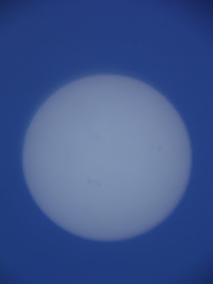
Below is an image of the Sun taken by GONG a little earlier. My image appears to be inverted.

The sunspots in the projected image appear to be a little clearer if the image is moving across the paper. This may be due to the graininess of the paper being less noticable in a moving image. I should also note that the objectives of the binoculars are 50mm lenses.

Below is an image of the Sun taken by GONG a little earlier. My image appears to be inverted.
The sunspots in the projected image appear to be a little clearer if the image is moving across the paper. This may be due to the graininess of the paper being less noticable in a moving image. I should also note that the objectives of the binoculars are 50mm lenses.
A Better View of the Sun
The skies were clearer today but still slightly milky blue. I was able to determine the focal length with the +1D lens combination more precisely.
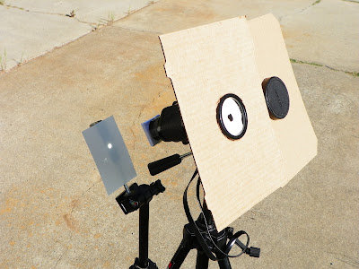
Placing the binoculars and screen on tripods allows for hands free observation. The binoculars were attached with rubber bands. Using a lower power lens system might enlarge the image a little more. With a 0.5D combination one might be able to double the image size.
There are simple and inexpensive ways of viewing an eclipse. Not everyone has a 10 inch telescope dedicated to solar observations for their use. For an outing easy setup is an advantage. Also in northern California one should consider bringing an umbrella and be prepared for a breeze on the beaches.
Wednesday, April 18, 2012
A Problem With Projecting The Sun's Image With Binoculars And Its Solution
I tried doing eyepiece projection with a pair of binoculars and found that they didn't focus the Sun's image of the very well. A small positive lens will converge the rays to form a better image. For a projective image the best focus for the binoculars by themselves occurs when the eyepiece is at its farthest extension. Again an aperture stop in front of the objective lens is needed to reduce the brightness of the image for ease of viewing.
I tried both a 2D (diopter) lens and a 1D = 3D + -2D combination from an Edmund Scientifics 38mm Demonstration Lens Set. With the 1D combination one can create an image 1 inch in diameter. The lens holder was a small "envelope" made from 20lb matte ink jet paper that was attached to the binoculars with cellophane tape.
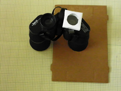
It helps to leave one of the lens caps on the binoculars and add a cardboard shade. An index card can be used as an imaging screen. The farther away the index card is the larger the image one gets. The aperture may need to be increased for larger images. I found it difficult to find the focal point. There were still some thin clouds out today.
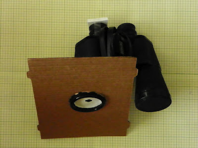
The binoculars are a pair of Galilean telescopes and so the eyepieces are diverging. They were designed to work close to the eye and adding a positive lens corrects the focusing problem. I tried taping the 1.50D clip-on reading glasses over both eyepieces and found that will work if one does not have a lens set available.
I tried both a 2D (diopter) lens and a 1D = 3D + -2D combination from an Edmund Scientifics 38mm Demonstration Lens Set. With the 1D combination one can create an image 1 inch in diameter. The lens holder was a small "envelope" made from 20lb matte ink jet paper that was attached to the binoculars with cellophane tape.

It helps to leave one of the lens caps on the binoculars and add a cardboard shade. An index card can be used as an imaging screen. The farther away the index card is the larger the image one gets. The aperture may need to be increased for larger images. I found it difficult to find the focal point. There were still some thin clouds out today.

The binoculars are a pair of Galilean telescopes and so the eyepieces are diverging. They were designed to work close to the eye and adding a positive lens corrects the focusing problem. I tried taping the 1.50D clip-on reading glasses over both eyepieces and found that will work if one does not have a lens set available.
Tuesday, April 17, 2012
Magnifying the Sun's Image
One can magnify the Sun's image by adding a diverging lens to the optical bench. The lens used was -6 diopters and was placed near the focal length of the reading glasses. The screen was moved further away from the lens to where the image was approximately in focus.
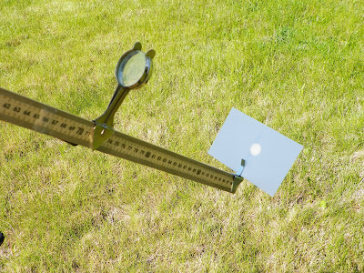
The aperture had to be increased with the paper hole punch to make more light available because for the larger image. There were some thin clouds near the Sun at the time the photo was taken which complicated matters somewhat but this shows how one can create a larger image. The combination of the two lenses forms a small Galilean telescope.

The aperture had to be increased with the paper hole punch to make more light available because for the larger image. There were some thin clouds near the Sun at the time the photo was taken which complicated matters somewhat but this shows how one can create a larger image. The combination of the two lenses forms a small Galilean telescope.
Imaging the Sun with Reading Glasses
This morning a pair of clip-on reading glasses arrived at my home from amazon.cm and I was able to make a simple device for imaging the Sun. The lenses are +1.50 diopters and I mounted them on an optical bench to illustrate the relation between the diopter power and the focal length which is 2/3 of a meter.
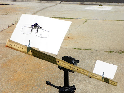
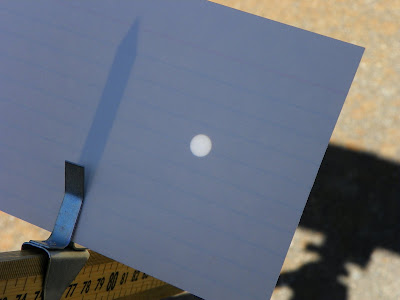
The small aperture in the index card reduces the brightness of the projected image and improves the sharpness of the image since the lenses were designed to work near the eye and so not all the rays from the glasses will focus correctly on the image card.
The reading glasses do help with working at the computer since I wear bifocals and have some presbyopia. The Visby lenses are evidence that some of my distant ancestors may also have suffered from this condition. These lenses were quite sophisticated for their time.

The small aperture in the index card reduces the brightness of the projected image and improves the sharpness of the image since the lenses were designed to work near the eye and so not all the rays from the glasses will focus correctly on the image card.

The reading glasses do help with working at the computer since I wear bifocals and have some presbyopia. The Visby lenses are evidence that some of my distant ancestors may also have suffered from this condition. These lenses were quite sophisticated for their time.
Friday, April 13, 2012
Problems With Reconstructing Pinhole Images
It can be difficult to see fine details in a B&W image and another way of viewing the simulated pinhole image is by looking at the changes instead. In the images below the changes between neighboring pixels were computed and stretch in the grey scale to fit between 0 and 255. The zero point was chosen to be 50% grey. White indicates a positive difference and black a negative difference.
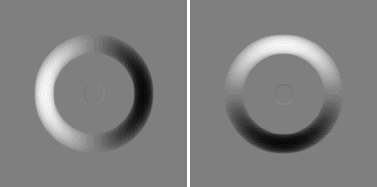
The two contrast images show how the small dark point at the center of the test object affects the pinhole image. There is a slight decrease when the aperture includes these points.
I also noticed a lot of round off errors in the aperture sums. The sums ranged from 0 to 317 (the number of aperture pixels) which were adjusted to fit between 0 and 255 for the image. Converting back to the original range produced the round off errors of ±1.
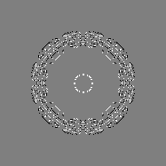
The errors occurred where the changes took place mainly within a range of ro±ra from the center of the disk where ro was the radius of the disk and ra was the radius of the aperture. The errors make it more difficult to reconstruct an image.

The two contrast images show how the small dark point at the center of the test object affects the pinhole image. There is a slight decrease when the aperture includes these points.
I also noticed a lot of round off errors in the aperture sums. The sums ranged from 0 to 317 (the number of aperture pixels) which were adjusted to fit between 0 and 255 for the image. Converting back to the original range produced the round off errors of ±1.

The errors occurred where the changes took place mainly within a range of ro±ra from the center of the disk where ro was the radius of the disk and ra was the radius of the aperture. The errors make it more difficult to reconstruct an image.
Wednesday, April 11, 2012
Correcting Pinhole Camera Images
The pinhole camera images may contain more image content than the number of aperture sized pixels would indicate. If one has an array of numbers which represent a test object one can generate the equivalent of a pinhole image by summing over a test aperture. In the example below the x values represent the object and x' an image obtained by using a 2x2 aperture.
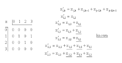
The calculations for a few of the image points, x'j,k, are shown. If rows and columns of buffer points with value zero are included about the test object points then only one object point contributes to the sum for each point in the first row of image points.
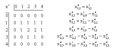
If we start out with a new array, x''j,k, in which the points are all zero we can substitute the sums over the aperture using the new array instead of the test object. Starting at the top left we can solve one step at a time for the unknown image points in the new array using values from the pinhole image.
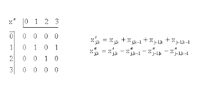
We get back the original pattern in the test image by doing one row at a time from top to bottom. In each case the new point is just the difference between the corresponding point in the pinhole image and a sum over known values in the partially completed reconstructed image.
To illustrate the process for more complicated images a test object was generated which contained a disk 101 lines in diameter. The simulated pinhole image was generated using a circular aperture 21 lines in diameter. While scanning from left to right and top to bottom if a nonzero point was encountered in the pinhole image the unknown image point was taken to be the position of the point of the aperture which was closest to the center of the disk in the pinhole image.
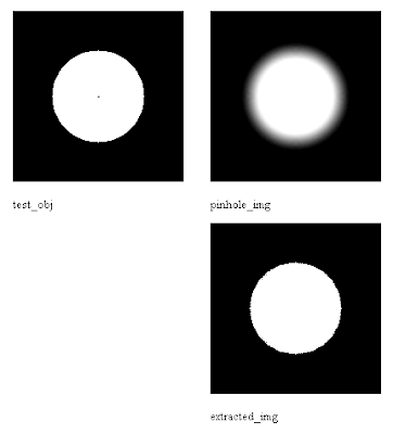
The extracted image shows a disk of the same diameter as the original but it did not contain the small dark spot in the center of the original image and also contained a few errors near the edge of the disk. The errors may be due to the scanning process or to the use of rounded values in the pinhole image.

The calculations for a few of the image points, x'j,k, are shown. If rows and columns of buffer points with value zero are included about the test object points then only one object point contributes to the sum for each point in the first row of image points.

If we start out with a new array, x''j,k, in which the points are all zero we can substitute the sums over the aperture using the new array instead of the test object. Starting at the top left we can solve one step at a time for the unknown image points in the new array using values from the pinhole image.

We get back the original pattern in the test image by doing one row at a time from top to bottom. In each case the new point is just the difference between the corresponding point in the pinhole image and a sum over known values in the partially completed reconstructed image.
To illustrate the process for more complicated images a test object was generated which contained a disk 101 lines in diameter. The simulated pinhole image was generated using a circular aperture 21 lines in diameter. While scanning from left to right and top to bottom if a nonzero point was encountered in the pinhole image the unknown image point was taken to be the position of the point of the aperture which was closest to the center of the disk in the pinhole image.

The extracted image shows a disk of the same diameter as the original but it did not contain the small dark spot in the center of the original image and also contained a few errors near the edge of the disk. The errors may be due to the scanning process or to the use of rounded values in the pinhole image.
Friday, April 6, 2012
The Sun's Image for an Aperture in the Shape of a Pythagorean Star
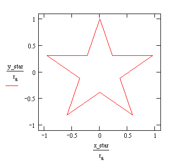
The shape of the aperture is quite arbitrary as said before and the Pythagorean star gives a result similar to those of the n-gons.
In the radial curves for the image the deviations for different values of the angle θ vary from a mean value and appear to be affected by the symmetry of the aperture. Both the Pythagorean star and the pentagon have five peak deviations.
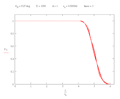

In the radial curves for the image the deviations for different values of the angle θ vary from a mean value and appear to be affected by the symmetry of the aperture. Both the Pythagorean star and the pentagon have five peak deviations.

Wednesday, April 4, 2012
"Triangular" Coordinates
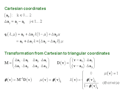
The coordinates used for a position in the aperture for the Sun image calculations are not readily found so it might be good to say a few words about them. I think of them as "triangular" coordinates and they are related to barycentric coordinates. They are defined with respect to the vertices of a triangle, ak, as illustrated in the image below. One starts projecting the position of an arbitrary point, q, from point the a2 onto the line connecting the first two points meeting it at q'. λ is then the fraction of the distance that q' makes from a0 to a1. Similarly μ is the fraction of the distance that q makes from q' to a2. So both λ and μ vary from 0 to 1.
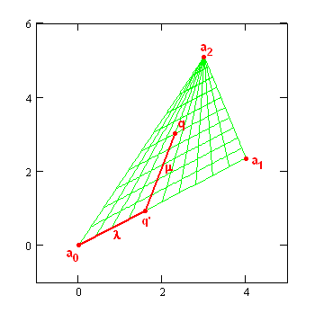
The properties of triangular coordinates are rather interesting. They are fairly easily transformed back and forth from ordinary Cartesian coordinates.
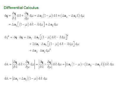
The fundamental forms for the line element and area are not very complicated.
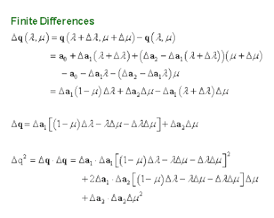
Also the distance between two triangular coordinates can be computed exactly using finite differences.
One can also extend the system to triangular pyramids as can be seen by the projection of a line from an image point through an aperture point. The projection of an arbitrary point in the pyramid onto a plane is unique as is the projection of a point onto a line.

The properties of triangular coordinates are rather interesting. They are fairly easily transformed back and forth from ordinary Cartesian coordinates.

The fundamental forms for the line element and area are not very complicated.

Also the distance between two triangular coordinates can be computed exactly using finite differences.

One can also extend the system to triangular pyramids as can be seen by the projection of a line from an image point through an aperture point. The projection of an arbitrary point in the pyramid onto a plane is unique as is the projection of a point onto a line.
Monday, April 2, 2012
The Relative Illuminance of Inscribed Polygons
One can compute the functions for the projected images of the Sun produced by light passing through known apertures. For the case of regular polygons (n-gons) some of the equations needed in Mathcad are shown in the image below. One can start by defining a point, p, in the image plane. The vertices of the n-gon aperture are designated by letter "a" and a point within the aperture is given by q. Δq' gives the distance of the projected image of q in the image plane onto an illuminating disk which represents the Sun. The integral, I, computes the sum of all the flux tubes illuminating a given spot on the screen. A''dλdμ is an element of area in the aperature and to see if its projection from the point on the screen contributes to the sum we have to add the condition that it be within an angular distance θS, the Sun's angular radius, from the center of the disk. Using a logic function is convenient since it is either 1 or 0 depending on whether or not the projected point contributes.
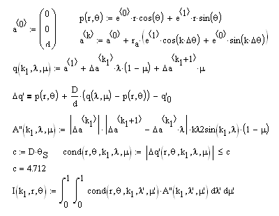
To simplify form of I(r,θ) the n-gon was divided up into n-1 triangles designated by k1. The entire area of the polygon is the sum, Σ, of n-1 such integrals. This allows one to compute a set of radial curves for various values of θ. One such set for an inscribed triangle is shown below with θ varying from 0° to 90°. The curves are constant when the projection is near the center of the disk but as one crosses its edges fewer points contribute and the curve is sloped as a result. As the number of sides in the aperture increases the resulting curves converge to those of a the circle.
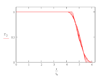
One can also compare the illumination from a number of n-gons inscribed in a circle of radius ra. In each case the integral for the aperture was divided by the area of the circle which is also found in the formula for the area of the inscribed n-gon, An.
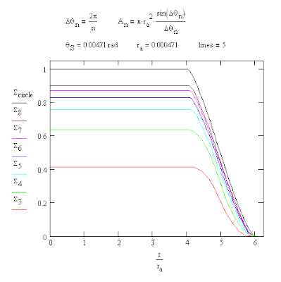
The maximum heights of the n-gon integral curves are in agreement with sin(Δθn)/Δθn. The total area under each of the integral curves is that of the n-gon used for the aperture. Note also that the width of the sloping sides of the illuminated image is equal to the width of the aperture or, in other words, the width of a "line."

To simplify form of I(r,θ) the n-gon was divided up into n-1 triangles designated by k1. The entire area of the polygon is the sum, Σ, of n-1 such integrals. This allows one to compute a set of radial curves for various values of θ. One such set for an inscribed triangle is shown below with θ varying from 0° to 90°. The curves are constant when the projection is near the center of the disk but as one crosses its edges fewer points contribute and the curve is sloped as a result. As the number of sides in the aperture increases the resulting curves converge to those of a the circle.

One can also compare the illumination from a number of n-gons inscribed in a circle of radius ra. In each case the integral for the aperture was divided by the area of the circle which is also found in the formula for the area of the inscribed n-gon, An.

The maximum heights of the n-gon integral curves are in agreement with sin(Δθn)/Δθn. The total area under each of the integral curves is that of the n-gon used for the aperture. Note also that the width of the sloping sides of the illuminated image is equal to the width of the aperture or, in other words, the width of a "line."
Subscribe to:
Comments (Atom)


